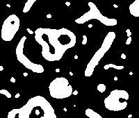
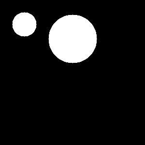
| INPUT: cell.pgm | DESCRIPTION OF THE PROBLEM |
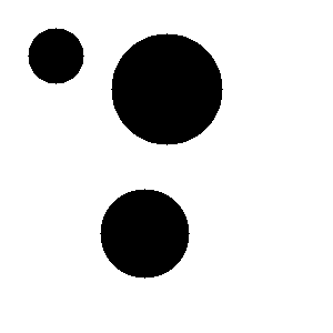
EXPECTED RESULT (1C) |
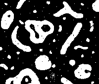 |
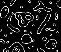
The small white spots and black holes in cell.pgm correspond to noise due to the acquisition process. They do not carry any information about the cells under study. Such noise is called (binary) salt and pepper noise or speckles. Problem 1 is about removing salt and pepper noise from this image. |
 |
Guideline.
- 1A - Remove the white spots (the smallest) visible in the black background.

- 1B - Remove the black holes within the white cells/blobs.
- 1C - Remove salt and pepper noise: produce an image like the one above on the right.
- 1D,E,F - Same goal as 1A,B,C but without "moving" the contours of the cells (to be done after step 2B).
Tools.
You could use (compositions of) the dilation and erosion programs that you have implemented during the first practical session of the course. Instead, to save time, you can use the programs of Pink Library, which are made available to you, through Linux terminals of the provided Working Environment:
- 'esedit.tcl'
- 'dilation'
- 'erosion'
- 'dilatball'
- 'erosball'
Additional Tools for solving two stars questions are shown at the end of the page.
Problem 2: Filling the holes of cell3.pgm
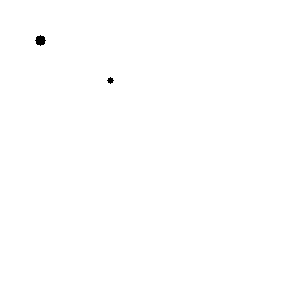
| INPUT: cell3.pgm | DESCRIPTION OF THE PROBLEM |
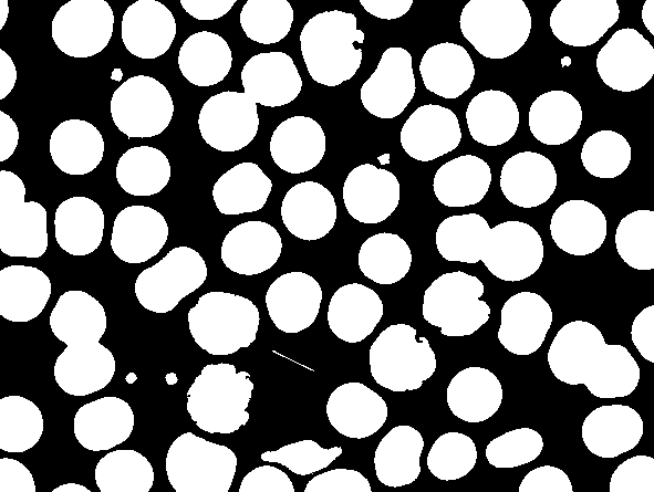
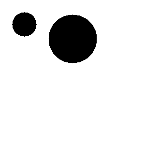
EXPECTED RESULT (2B) |
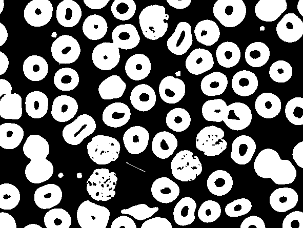 |
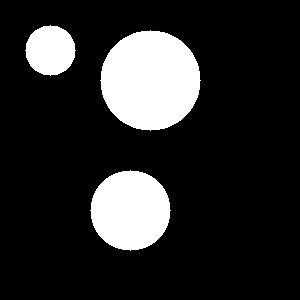
Image cell3.pgm contains cells (in white). The absence/presence/number of holes allows different kinds of cells to be distinguished. A first step towards identification of the different cells consists of extracting the holes. This can be done by i) filling all holes; and ii) taking the difference between the initial image and the one without holes. Problem 2 is about filling the holes of cell3.pgm |
 |
Guideline.
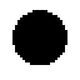
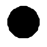
- 2A - Fill the black holes in the interior of the white blobs or cells.
- 2B - Fill the holes while preserving the shape of the external contours of the cells exactly as in the original image (see for instance the expected result shown above). To reach this goal, use operaor geodilat.


